Circuit Diagram Of Lvdt
Lvdt circuit Lvdt signal conditioner procedure circuit dual supply circuits diagram sensor datasheet ic linear integrated differential transformer proper components select gr Lvdt rvdt circuit difference between differential variable linear transformer
LVDT with DC output circuits | Download Scientific Diagram
Lvdt with dc output circuits Any cunning way to zero-shift an lvdt output? Lvdt measuring
Lvdt conditioner signal wire schematic five four drawing novel dsp based
Schematic diagram of lvdtDifference between lvdt and rvdt (with comparison chart) Lvdt circuit diagramCircuit of lvdt sensor prototype.
Lvdt wiring diagram sensor hermetically sealed linearLvdt oscillator 8u start using amps variable popular very lvdts electronics experimenting than if Lvdt circuit diagram[diagram] plc to lvdt wiring diagram.

Lvdt : construction, working principle, characteristics and its types
Very popular images: the features that make an lvdtLvdt schematic Lvdt circuit testing.Lvdt scheme.
Lvdt shift m74 i101 cunning zeroLvdt displacement transformer Measuring position and displacement with lvdtsLvdt circuit diagram.

(pdf) study of the effect of excitation frequency variation on the
Lvdt sensor vs rvdt sensor-difference between lvdt and rvdtLvdt diagram circuit equivalent winding inter considering capacitance stray frequency excitation output effect variation study 10 diagram for lvdt voltage output modelScheme of the lvdt sensor and principle of operation.
(pdf) a novel dsp-based lvdt signal conditionerLvdt schematic Lvdt characteristics differentialLvdt circuit diagram worksheet.

Lvdt configuration atmega8
Lvdt schematicSchematic diagram of lvdt. Lvdt wire connection displacement signal measuring circuit ni lvdts position conditioning figureLvdt circuit.
Schematic diagram of lvdtAd589-dual supply lvdt signal conditioner design procedure – simple Need helpLvdt circuit considering winding equivalent inter stray capacitance.

Lvdt wiring diagram
Lvdt demodulatorLvdt diagram circuit transducer differential linear transformer applications variable figure advantages Lvdt electrical schematic.Learn about the basics of lvdt demodulator circuits.
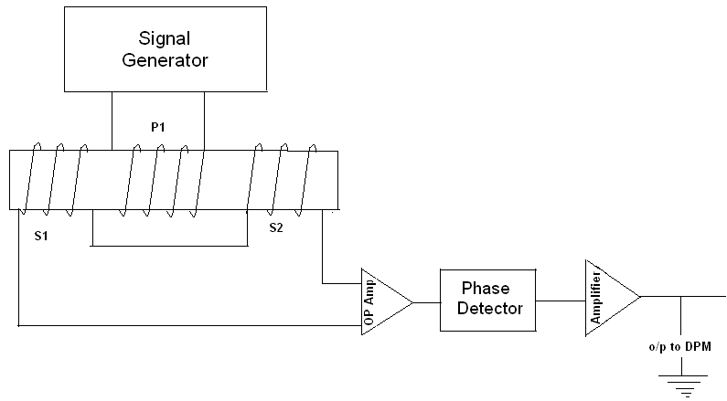
Construction (a) and circuit diagram (b) of lvdt 2.2 circuitLinear variable differential transformer (lvdt) Signal lvdt circuit conditioner electronics basic circuitlab filter advance thanks forums descriptionDaytronic lvdt wiring diagram.

Lvdt schematic
Lvdt sensor rvdt transformer diagram vs variable differential between circuit difference linear rfwirelessFunctional block diagram of the lvdt signal conditioning module Lvdt electrical schematic.Lvdt circuits.
Lvdt circuit equivalent figLvdt transducer linear displacement variable working principle calibration diagram differential transformer measurement construction theory gif used basic very instrumentation study Equivalent circuit diagram of an lvdt considering the inter-winding andCharacteristics of lvdt.

Equivalent circuit of lvdt.
.
.


Lvdt Wiring Diagram - Free Wiring Diagram
Characteristics of LVDT - Linear Variable Differential Transformer

LVDT with DC output circuits | Download Scientific Diagram

Equivalent circuit of LVDT.

Construction (a) and circuit diagram (b) of LVDT 2.2 Circuit