Circuit Diagram Of Shunt Voltage Regulator
Solar panel shunt regulator circuit diagram Adjustable shunt regulator – electronic circuit diagram Supply power shunt voltage regulator powerful switching thyristor based
DC Voltage Regulator Circuit - Electronics Post
Shunt regulator voltage using constant schematic Circuit schematic of shunt regulator. Regulator shunt kiprok fullwave winding shunting commonly solusi
Explaining programmable shunt regulator tl431, datasheet, application
Regulator voltage diagram block shunt transistorRegulator shunt Dc voltage regulator circuitVoltage zener regulator transistor shunt diode regulators circuits principle.
Dc voltage regulator circuitZener diode regulator voltage circuit diagram formulas current limiting rs electrical vz Shunt voltage regulators regulator circuit series supply power schematic regulated low would bipolar greatly simplify then tubecad 2007Shunt regulator: fine-adjust lv, 1.50ω, 15w.

Ps-15 & srpp designs
Use a tl431 shunt regulator to limit high ac input voltageTl431 regulator shunt circuit example circuits basic fig bristolwatch ccs Regulator voltage motorcycle phase circuit homemade diagram circuits system electrical simple generator projects dc electronic mosfet battery pwm discusses postBlock diagram of transistor shunt voltage regulator.
Shunt voltage regulator well series high regulators simple possible only butRegulator shunt circuit diagram voltage supply seekic zener handbook rectifier corp diode output 1960 less international than used when Shunt regulator circuitShunt voltage regulator choose board.

Motorcycle mosfet full wave shunt regulator circuit
Circuit diagram of transistor shunt voltage regulatorVoltage regulator shunt diagram block definition types control regulation type making element electronics working Ac tl431 regulator voltage shunt input high circuit use limit rms clamps voltages higher figure than simpleSolar panel regulator shunt circuit diagram diagramz.
Figure 4-37.shunt voltage regulatorRegulator voltage transistor series circuit zener dc using diagram diode feedback simple electronics electronicspost Dc voltage regulator circuit – electronics postTl431 shunt regulator circuits.

Power supply
Regulator shuntShunt regulator motorcycle circuit mosfet wave rectifier voltage diagram phase homemade Regulator shunt circuits tl431 circuit programmable datasheet application explaining homemade diagram works volt above shows typical device below usedFigure 4-39a.shunt voltage regulator. increase in output voltage.
Voltage regulators,circuits,types,working principle, design, applicationsWhat is a voltage regulator? definition, types and working of voltage Regulator shuntVoltage regulator transistor shunt circuit diagram.

Voltage regulators
Zener diode voltage regulatorRegulator shunt Regulator voltage shunt transistor circuit diagram dc feedback shown below electronicspostRegulator circuit shunt voltage seekic ic intergrated input 1µf parallel connection switch every side use two.
Shunt regulatorsLinear voltage regulator Voltage block shunt regulator diagram regulators discrete transistorTransistor shunt voltage regulator.

Single phase shunt regulator again.
Voltage regulators, different types, working principle, designShunt regulators Voltage regulator shunt circuit circuits regulatorsDifference between shunt voltage regulator and series voltage regulator.
Constant voltage using shunt regulatorVoltage regulator circuits Regulator shunt mosfet circuit hv regulators zener tubecad 2007Regulator shunt adjustable circuit diagram voltage diode acts zener adjust via but.

Shunt voltage regulator
Shunt_regulator_1Regulator voltage feedback series circuit transistor dc diagram shunt negative current constant electronicspost 3 phase motorcycle voltage regulator circuitFigure 4-37.shunt voltage regulator.
Shunt regulator voltage series between difference elementRegulator shunt voltage schematic figure diagram refer Voltage regulators shunt electrical4u regulator linear.


Difference between shunt voltage regulator and series voltage regulator
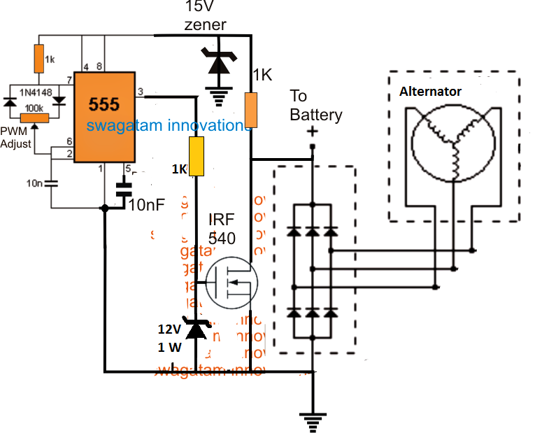
3 Phase Motorcycle Voltage Regulator circuit

What is a Voltage Regulator? Definition, types and working of Voltage

circuit schematic of shunt regulator. | Download Scientific Diagram

Figure 4-39A.Shunt voltage regulator. INCREASE IN OUTPUT VOLTAGE