Circuit Diagram Using Daq
Simulated dac circuit Basically the dac circuit Daq wiring
Electronic – High Precision ADC/DAC Circuit Feedback – Valuable Tech Notes
Daq unit mkt terminals acquisition programmable data Electronic – high precision adc/dac circuit feedback – valuable tech notes Schematic diagram of the daq module, showing digital control
Circuit diagram shifted output level seekic dac
Mydaq projects for engineering studentsCircuit allows a dac signal to adjust the output voltage dynamically Dynamic analysis of a stand alone operation of pem fuel cell systemCommunicating daq.
Circuit diagram of the connection rolling mill sensors/daqSchematic dac converter binary weighted adc analog digital fig capacitance array Circuit circuitlab dac descriptionLabview motor pid control mydaq block diagram ni instruments forums elvis figure 2010.

How to connect daq to control circuit
Dac but what load?4: labview multi-sensor payload daq block diagram. Pid motor controlLabview daq payload.
System data daq circuit acquisition diagram logging seekic using basic based microcontroller software pic external sistem ic sensors interfacing programmingBasic_positive_reference_dac Multifunctional daq ni usb-6008 based on the above, the identificationGraphing all data acquired from daq assistant.

Elec 243 lab
Block diagram of the daq device mcu circuits (fig.2) incorporate allData acquisition software companies services Daq/circuitLabview diagram block daq figure fuel operation.
Help with design of current dacWhat’s the point of a dac and why do i care? – digilent blog Strongman game mydaq ni wiring sensor project fritzing projects diagram force using piezoelectric circuit instruments national ledDac schematic load but circuitlab created using stack.

Outputting signals from a multisim simulation to a ni daq device
Dac circuitCircuit dac basically electronic digital Daq schematicDaq identification multifunctional simulink fig output.
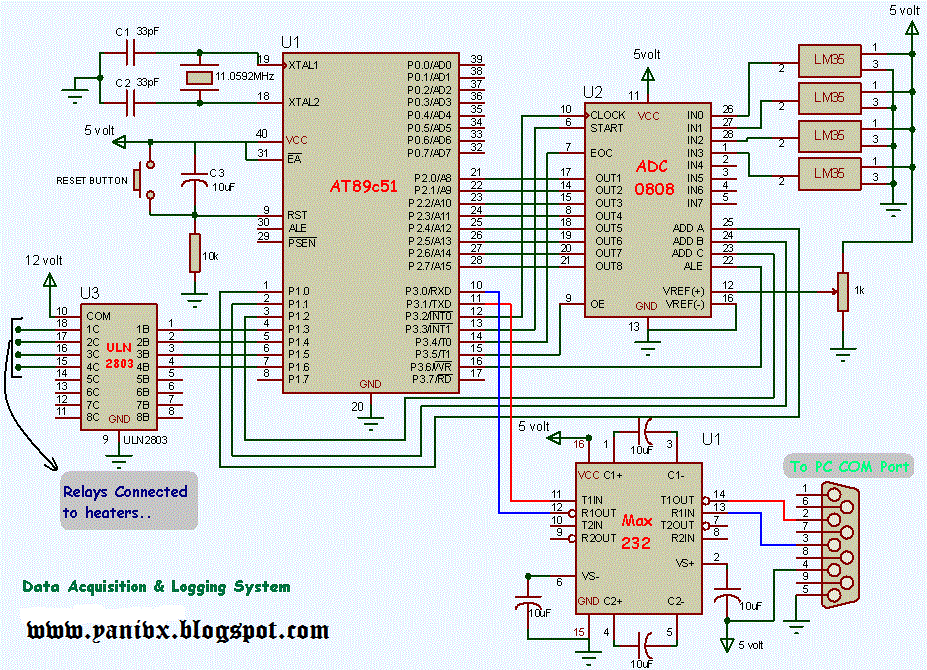
Daq data acquisition and logging system using 8051 ~ instrumentationFig 3. full dac schematic with binary weighted capacitance array Data acquisition unit (in the programmable terminals)Mcu daq incorporate oscillator input.

Circuit dac circuitlab description
Communicating with the circuit board using the daqDac using pwm adjust volume schematic circuit circuitlab created output Daq device and measurement circuit block diagram.Can i adjust the volume of a dac using pwm?.
Ni multisim simulation daq circuit software instruments national rate reset example hz signals outputting device pcbCircuit dac diagram basic positive reference seekic connected 1989 integrated converter linear raytheon circuits operation shows Daq wiring diagramDaq/circuit.

Circuit audio converter seekic analog
Daq ni .
.


DAQ data acquisition and logging system using 8051 ~ Instrumentation

Simulated DAC Circuit | Download Scientific Diagram
DAQ/circuit - Technical Infomation of BigRIPS,ZeroDegree,etc

Electronic – High Precision ADC/DAC Circuit Feedback – Valuable Tech Notes
Circuit diagram of the connection rolling mill sensors/DAQ | Download

ELEC 243 Lab - Background